
Excitation Systems
Excitation systems provide field current to the rotor winding of a generator. A well-designed excitation system ensures reliability, stability, and fast transient response. This article explores four common excitation methods and their applications, including diagrams and illustrations.
The four common excitation methods include:
- Shunt or Self-Excited
- Excitation Boost System (EBS)
- Permanent Magnet Generator (PMG)
- Auxiliary Winding (AUX)
Each method uses an Automatic Voltage Regulator (AVR) to supply DC output to the exciter stator. The exciter rotor’s AC output is rectified to DC input for the main generator rotor. Advanced systems may include additional inputs to the AVR.
Automatic Voltage Regulator (AVR)
The AVR construction varies with the excitation method used. Key types of AVRs include:
- Silicone Controlled Rectifier (SCR): Determines exciter voltage using stator power levels; may struggle with non-linear loads.
- Field Effect Transistor (FET): Translates stator power levels into Pulse Width Modulated (PWM) signals; handles non-linear loads effectively.
Excitation Methods
Shunt or Self-Excited
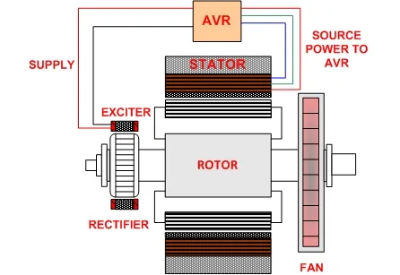
Key Features
- Simple, cost-effective design.
- Input power is directly supplied to the AVR from the stator.
- Fewer components make troubleshooting easier.
Drawbacks
- Voltage decreases with load increase, pushing the AVR to its limits.
- Not suitable for non-linear loads, which may cause excitation field breakdowns.
- Susceptible to power loss during short circuits.
Applications
- Best for linear loads (constant load).
- Avoid non-linear load applications.
Excitation Boost System (EBS)
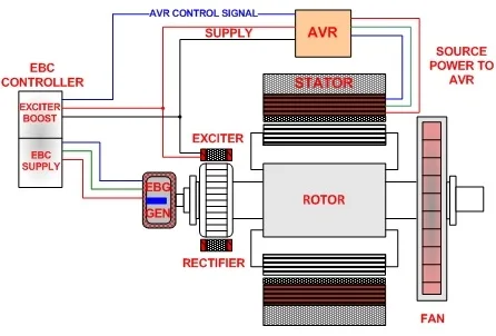
Components
- Excitation Boost Control (EBC) Module
- Excitation Boost Generator (EBG) mounted on the alternator’s driven end.
Functionality
- Provides additional excitation current when required.
- Designed for emergency or backup power applications.
- Improves performance with non-linear loads like motor startups.
Drawbacks
- Not recommended for continuous power applications.
Permanent Magnet Generator (PMG)
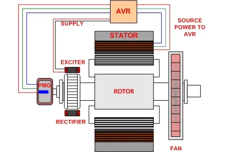
Key Features
- Equipped with a permanent magnet on the driven end of the generator shaft.
- Produces a clean, isolated, uninterrupted 3-phase waveform.
Benefits
- Sustained short-circuit fault clearance.
- Unaffected by changing loads.
- Reliable voltage on initial startup.
Applications
- Ideal for non-linear loads, including motor startups.
- Common in generators handling variable loads.
Auxiliary Winding (AUX)
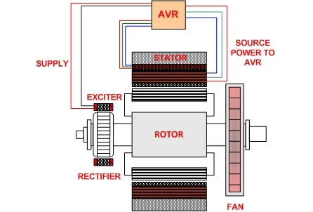
Functionality
- Incorporates additional single-phase windings into the stator.
- Provides extra excitation voltage for non-linear loads.
Applications
- Suitable for marine and industrial applications.
- Practical for larger installations.
Choosing the Right Excitation Method
- Linear Load Applications: Shunt, EBS, PMG, or AUX methods can be used; shunt is the most cost-effective.
- Non-Linear Load Applications: EBS, PMG, and AUX methods are preferred; PMG is the most widely used.