This article provides information, illustrations, and detailed examples to assist in planning for the installation of a large industrial generator set at your facility or worksite. We pick up and continue to expand on the previous Site Planning for an Industrial Generator Installation article.
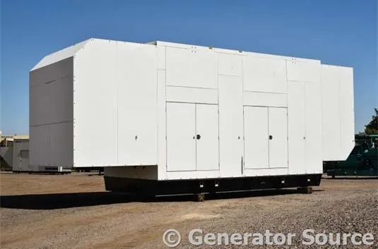
Caterpillar 1500 kW Outdoor Generator
In this article, additional tips for site preparation and project management are included, as well as details on fuel systems and some initial electrical connection considerations.
Generator Applications Covered:
- Permanent Enclosed Generator – Outdoor installation of a canopy generator system, including setting and connecting the generator and auxiliary fuel system.
- Generator Located Inside Factory – Indoor installation of a generator system on a skid, including setting the generator and connection of auxiliary systems.
- Portable Enclosed Generator – Basic inspection/setup and power system installation diagrams.
Permanent Enclosed Generator
Setting the Generator
A reinforced concrete pad with generator mounting studs has been installed, and the concrete has had appropriate time to set. The generator set has been unloaded and is ready to set on the concrete pad.
WARNING:
This generator set requires a crane to move. To reduce the possibility of personal injury, always use lifting equipment with the proper capacity. Assistance is recommended when aligning the generator set.
Factors to Consider for Setting the Generator:
- Use a lifting device to safely lift and place the generator set level on the concrete pad.
- Ensure the crane has the capacity to place the generator set on the pad.
Sequence for Setting the Generator:
- Connect the generator set to a lifting device and crane.
- Move and align the generator set with the concrete mounting studs.
- Install attaching hardware (washer, lock washer, nut).
- Fuel generator tanks.
- Connect generator output to the Automatic Transfer Switch (ATS).
Setting Auxiliary Fuel Tanks
Generator Fuel Rates:
- 22 GPH at 25% load ÷ 1600 gallons = 72 hours of operation.
- 71 GPH at 100% load ÷ 1600 gallons = 22 hours of operation.
Auxiliary fuel tanks extend operation time during major power outages, such as extreme weather or power grid failures.
Sequence for Setting Auxiliary Fuel Tank:
- Locate the fuel tank, align it with mounting studs, and install washers and nuts.
- Install the fuel pump and filter assembly onto the tank.
- Install a retractable hose reel and connect it to the fuel pump.
- Fuel the auxiliary tank and all fluids.
- Connect the fuel pump electrical supply to the switchboard (supplied by the generator in emergencies).
Generator Inside Factory
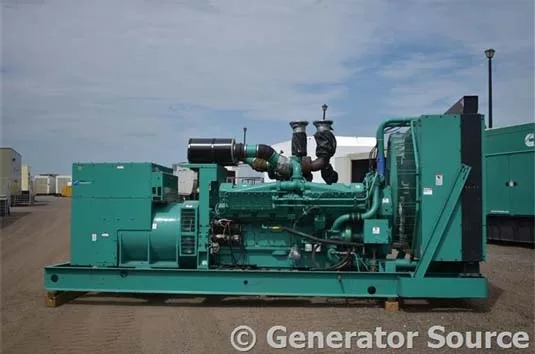
Cummins 1250 kW Indoor Generator
A Cummins 1250 kW generator set is selected for the facility, placed on a skid as a complete unit. The generator is a replacement for a previous generator that experienced catastrophic failure.
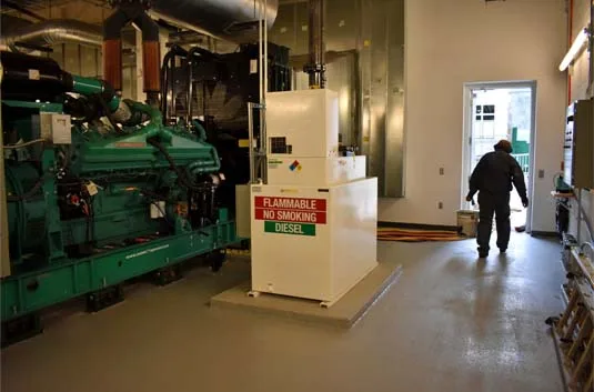
Setting the Generator
A Cummins 1250 kW generator weighs 25,000 lbs. A gantry supports the removal and installation of large equipment.
Sequence:
- Contract a crane company to unload and position the generator.
- Use the gantry to place the generator set onto the pad.
Connecting Auxiliary Systems
Systems to Be Connected:
- Exhaust Systems – Proper insulation and EPA compliance.
- Cooling Air – Louvers installed on the building’s exterior connected to the generator’s radiator/aftercooler.
- Fuel System – Proper fuel line connections and transfer pump setup.
- Electrical Systems – Full electrical integration with the generator’s control panel, output, and louvers.
- Intake Air – Adequate supply air for full-load operation.
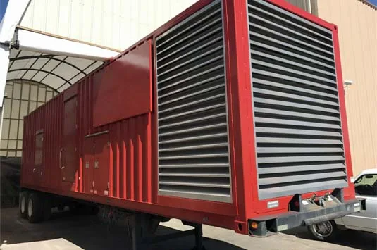
Portable Enclosed Generator
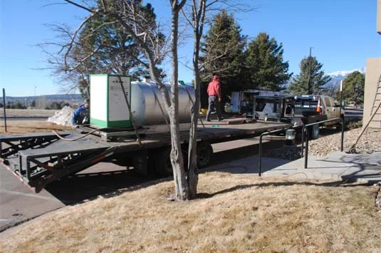
Inspection After Transport
When the portable generator arrives onsite:
- Ensure the generator is in a flat, stable area.
- Fuel tanks, fluid levels, and lifting gear should meet requirements.
- Perform pre-start and inspection for leaks.
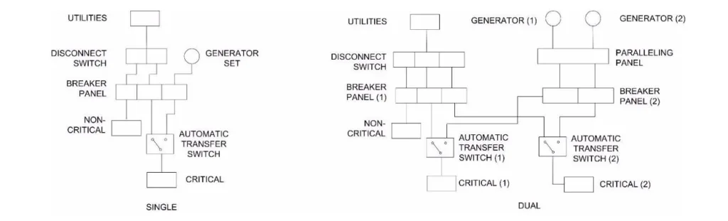
Electrical Connection Options
Single Generator Setup:
- Disconnect switch supplies power to the breaker panel.
- Automatic transfer switch enables critical power supply during outages.
Dual Generator Setup:
- Generators supply power through a paralleling panel.
- Expanded breaker panels accommodate both generators.
- Use two automatic transfer switches to separate loads effectively.