
Introduction to Sound and Noise
When dealing with large engine-driven equipment on a job site, one of the most overlooked issues is sound level. In the truest sense of the word, a sound wave can be defined as any disturbance that is propagated in an elastic medium, which may be a solid, liquid, or gas. Noise can be defined as any unwanted sound perceived by the hearing sense of human beings. Worker exposure to excessive or repetitive noise over a long period of time can result in hearing loss. The creation of an excessive source of noise into an environment can be potentially hazardous, as well as unpleasant to nearby commercial tenants and residents. Excessive noise control measures have been enacted at the national and local levels to maintain both safety and peace of mind. Typically, regulations are bundled together based upon the land use characteristics and the proximity to residential or other delicate areas.
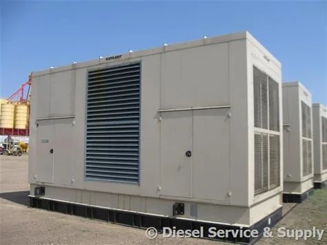
Sound Attenuated Enclosure
Noise control containment involves a system composed of three basic fundamentals: sound, path, and receiver. Before a solution to a complex noise problem can be designed, the dominant source of noise pollution must be known, the characteristics of the transmission path must be discovered, and an acceptable level of noise permitted must be established.
During the installation of an electrical generating system, many field factors can add to deviations of actual Sound Power Levels (SPL: Total sound radiated from a source with respect to a reference power of Watts) versus predicted levels of sound. The noise that is present in the natural environment of the genset prior to installation is referred to as ambient noise. The ambient, or background noise, should be measured and calculated before the installation of equipment. Therefore, a margin of safety should be applied to calculated values if all field conditions are not fully studied. For example, buildings, walls, signs, and auxiliary equipment commonly change the sound field. Obstacles within the sound path will partially reflect, absorb, and transmit sound. It is important to study field conditions and know the local decibel laws before embarking on an electrical generation project.
Sound Transmission Through Solids and Liquids
Sound waves need to be not only accounted for in the air but in solid and liquid forms as well. Airborne sound is typically created by the vibration in solids or turbulence in fluids. It is important to note that sound waves in solids and liquids can travel great distances before producing audible sound in the air. An example of vibrational noise would be the ability to hear a train through the rails at a long distance prior to the airborne transmission of sound waves. It is this type of sound transmission that often makes it difficult to acoustically isolate generator sets. Without adequate vibration isolation of the skid base on a generator, vibrations will travel unopposed through the skid, so that much of the noise is not subjected to acoustic dampening systems designed into the sound attenuated enclosure.
Mounting and Isolation Solutions
Ideally, used generators should be mounted on isolators, or on a concrete pad with the sound attenuated enclosure completely surrounding the base of the unit. Even small leakages in the system can contribute greatly to overall sound levels. Gaskets should be considered to prevent any noise leaks through gaps in an uneven concrete surface or around enclosure obstructions. Fluid flowing through pipes can also produce radiated sound that can be transmitted through a building or enclosed structure. Sound attenuation can be applied through rigid couplings for pipes and electrical connectors. Where needed, connections should be flexible or isolated enough to prevent transmission or vibration to the sound attenuated enclosure walls.
Commonly Used Sound Absorption Materials
When sound waves are produced, they are naturally reflected when they hit a hard surface. Installing an absorption surface over hard surfaces in most generators can reduce some of the reflected sound. In a room with hard surfaces, soft materials such as absorbent ceiling panels, floor rugs or carpeting, and blinds or special absorbent wall coverings, will reduce noise by reflecting sound. Only reflected sound can be muffled as described, while directed sound will not be directly affected in any way.
The vast majority of sound absorption composites are comprised of porous materials of varying density, which convert sound energy into heat within the open pores of the material. When researching sound muffling insulators, it is best to look for materials with air channels that are open to the surface so that sound waves can propagate into the material. If pores are sealed, as in closed-cell foam, the material is generally a poor absorber. Any pores should not be sealed by paint, coverings, or any protective coverings. Structural integrity shielding for sound absorption material should always be perforated if applied.
Key Factors for Sound Absorption
When beginning the material evaluation process prior to a project, a few key factors must be considered. The main metric when measuring for sound absorption boils down to a material’s ability to absorb energy defined as the absorption coefficient. The absorption coefficient is mathematically defined as the ratio of sound energy waves absorbed by a given surface in relation to the sound energy incident upon the surface. The absorption coefficient can vary between 0 and 1. For example, a = 0.8, then 80% of the sound energy will be absorbed. Another way to view sound coefficient levels is by looking at an open door or window. Sound waves are absorbed through the opening of the window 100%, a = 1, versus being reflected back into the room. The absorption coefficient is wholly dependent on frequency, and is usually printed for either an octave or 1/3 octave bands. Porous engineered sound absorbers are most efficient at higher frequencies, while improving the material’s thickness, or mass, can increase low-frequency absorption.
Low Frequency Sound Absorption Solutions
When low-frequency sound absorption is needed, panel sound absorption materials often are the solution. Thin, flexible panels are mounted away from the wall, creating a shallow air cavity between the material of the two. This air pocket between the panel and wall creates a means for sound absorption at commonly tuned low frequencies. Sound waves, at the frequency of interest, produce a resonating effect within the air pocket which causes the panel to vibrate. By simply filling the cavity with a secondary porous material, one can reduce the sharpness of the tuning. This type of sound attenuation solution can be inhibitive and is usually used to treat a specific tone or narrow band from the offending source of sound.
Traditional Sound Absorption System
The traditional approach to sound attenuation utilizes a sound-absorbing material sandwiched between a perforated lining and the external structure. The perforated lining typically consists of various patterns with small evenly spaced holes that can effectively absorb sound at common “tuned” frequencies. Medium and larger perforations are used for lower-pitched frequencies but are not as commonly used. The perforated facing is constructed on the top of the porous sound-absorbing material. Depending on the thickness, spacing, and hole size, the facing can also increase absorption to the overall structure at certain frequencies. Most high-frequency sounds are reduced significantly using this system because of reflections from the solid areas of the facing. A perforated facing design where the open cavity is at least 20% of the overall material will not significantly degrade the absorption of high-frequency sound over the typical range. Anything over 20% will have an impact on the overall absorption of sound.
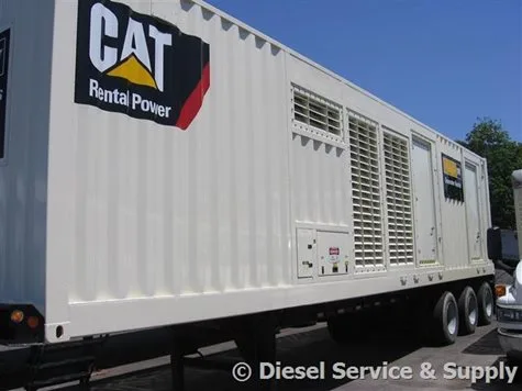
Sound Attenuated Generator Set Structures
When a generator enclosure requires sound attenuation, it’s essential to gather mechanical and combustion air exhaust data before making a purchasing decision. This data, often provided by the manufacturer, will indicate noise levels in decibels at a specific distance from the noise source and may include a full noise spectrum analysis that an enclosure manufacturer can interpret. Additionally, the noise rating of the radiator, including remote radiators, should be considered.
Keep in mind that dimensions, noise, and airflow requirements can vary significantly between manufacturers for a given kW rating. For instance, a 2013 800 kW generator may produce a different noise pattern than a 2004 800 kW generator. Therefore, when sizing enclosures for multiple generators, it’s advisable to base decisions on the worst-case data to ensure the sound-attenuated enclosures work across all generators.
Basics of Mass Law
Mass law refers to the transmission loss of particles in solid panels. It states that within a limited frequency range, the magnitude of the loss is controlled by the mass per unit area of the wall. The basic principle is that transmission loss increases by 6 decibels for each doubling of frequency or wall mass per unit area, up to a plateau for a given frequency. For example, a 1/8-inch thick lead sheet would result in a higher transmission loss than a 1/16-inch thick sheet. A combination of lightweight materials and mass layers is often used to achieve the desired sound attenuation.
Noise Resonance
All materials, whether natural or man-made, have a resonance frequency based on characteristics like mass. Lightweight skid mounting structures for generators can amplify noise levels due to vibrations caused by the engine’s forcing frequency. This can create a “drumming” effect that amplifies the sound. When selecting a generator, it’s crucial to consider vibration isolators, which are essential in damping the forcing frequency of the engine and isolating it from the structure.
Coverings
To prevent burns and excessive heat loss, machine components and connecting piping often come with thermal insulating wrappings. For noise reduction, a combination of acoustical and thermal insulation is sometimes used. Materials like foam composites or chemical sprays are common for wrapping pipes and other metal components of generators.
Mufflers/Noise Silencers
Noise silencers are essential for controlling noise from engine combustion, fans, and blowers. These silencers come in three types: reactive, absorptive, and a combination of both. Reactive silencers are best for absorbing low-frequency noise, while absorptive silencers excel at higher frequencies. A design that combines both types can provide comprehensive noise reduction. The choice of silencer depends on factors such as flow rate, noise spectrum, temperature, humidity, and allowable backpressure.
Most Common Sound Attenuated Enclosures
The most common way to muffle noise from generators is through acoustical enclosures. These enclosures typically consist of multi-layered panels that include an impervious exterior layer and a porous sound absorption layer facing the inside of the equipment. The absorption layer dissipates sound energy and also offers heat insulation. Maintenance is usually performed from outside via hinged doors and air intake louvers.
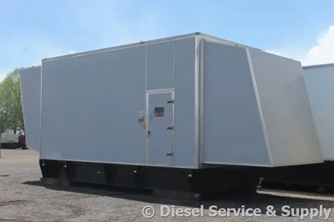
Weather-Proof vs. Weather-Protective Enclosures
It’s essential to determine whether a weatherproof or weather-protective enclosure is required. Weather-protective enclosures are used to shield the generator from rain and snow under normal conditions. In extreme environments, a weatherproof enclosure is needed, which can withstand wind, precipitation, and extreme temperatures. Weatherproof enclosures must meet stringent standards, such as resisting hurricane-force winds and heavy snow loads without permanent damage.
Generator Enclosure Construction
Generator enclosures come in various designs depending on the intended use and cost considerations. Common construction methods include:
- Bolted: Constructed from metal panels bolted, riveted, or screwed together.
- Welded: Fabricated metal elements welded together and overlaid with sheet metal.
- Pre-fabricated Panels: Pre-manufactured panels that form the roof and sides of the enclosure.
- Stressed Skin/Semi-Monocoque: A lightweight, durable structure with a skin and structural lining that become load-bearing elements.
Generator Enclosure Materials
Choosing the right materials for a generator enclosure involves balancing initial costs with long-term maintenance and considering the geographical location of the generator. The most common materials used for enclosures are selected based on their strength, cost, and ability to handle both noise attenuation and protection from the environment.
Sound Attenuation Recommendations
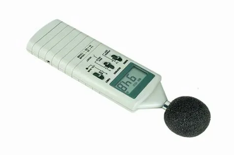
To determine the necessary sound attenuation for a generator, consider the site’s noise requirements early in the research phase. Using a portable digital decibel meter or real-time sound analyzer can help measure noise levels accurately. It’s also essential to account for local noise ordinances and the impact of site layout, such as nearby structures or vegetation, on sound propagation. When making a decision about sound attenuation, it is critical to understand how far the generator will be from property lines, as this will influence the type of enclosure needed.
By following these guidelines and understanding the key components and materials involved, it becomes easier to make informed decisions when selecting a generator enclosure that meets the noise reduction and environmental protection requirements.