
Overview of Generator Grounding
The Occupational Health and Safety Administration (OSHA) requires all combustion engine-driven generators to be grounded to the earth. This includes both stationary and portable models serving emergency, prime, and continuous applications.
Impedance grounding of the generator provides both safety and equipment benefits:
- Reduces burning and melting effects in electrical equipment (switchgear, transformers, cables, and rotating machines) during ground faults.
- Reduces mechanical shock in components and circuits exposed to ground faults.
- Reduces electrical shock hazards to personnel near the fault.
- Reduces line voltage dip that can occur when clearing a ground fault.
- Secures control of transient over-voltages while avoiding a facility shutdown.
This article outlines common methods for grounding a generator. Transformer and capacitor configurations are often used in impedance grounding configurations, with the transformer configuration featured here. Always consult a certified electrician or electrical contractor to ensure safe and proper grounding of your generator set before operation.
Generator Grounding Methods
Direct Earth Grounding
The direct earth grounding method is the simplest. In this method, a grounding wire or strap is attached to the alternator on one end and an earth ground on the other. This method is commonly used in small portable generator applications.
Impedance Grounding
Impedance grounding configurations are typically used for larger applications. Impedance is defined as the total resistance the circuit offers when energized. Components like transformers, conductors, grounding rods, and electronic components provide resistance in the grounding circuits.
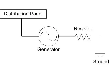
Low Impedance Grounding
Low impedance grounding involves installing a resistor between the generator and the grounding rod. This resistor is called a neutral grounding resistor, which limits the fault current when one phase of the circuit shorts or arcs to the ground.
- Resistor specifications: Often limits current to 200-400 amps. For example, a 1200V L-N, 200A 10-second resistor.
- Continuous load handling: A 200-amp resistor can handle 20 amps continuously without overheating.
Key Considerations for Low Impedance Grounding:
- Phase-to-ground currents are limited to 200-400 amps.
- Reduces arcing and arc flash hazards associated with phase-to-ground faults.
- Reduces damage to the rotor and stator.
- Does not prevent operation of overcurrent devices.
- Ground fault detection system is not required.
- Suitable for medium or high-voltage systems.
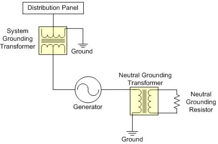
High Impedance Grounding
High impedance grounding circuits use a neutral grounding transformer for generator protection. The generator ground is connected to the input of the primary winding of the neutral grounding transformer, which supplies a path to ground in case of a system fault.
Key Considerations for High Impedance Grounding:
- Phase-to-ground currents are limited to 5-10 amps.
- Reduces arcing and arc flash hazards associated with phase-to-ground faults.
- Eliminates damage to rotor and stator.
- Prevents operation of overcurrent devices until the fault can be located.
- Requires a ground fault detection system.
- Suitable for low or medium voltage systems.
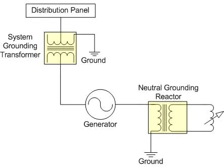
Compensated Grounding
Compensated grounding, also referred to as reactance or resonant systems, is designed similarly to high impedance systems. The key difference is that a neutral grounding reactor is used instead of a neutral grounding transformer and resistor.
Key Features of Compensated Grounding:
- More expensive due to the addition of a neutral grounding reactor.
- Uses a system grounding transformer for system grounds.
- Ground fault currents can be less than 1 amp.
- The reactor is tuned against generator capacitance to ground.
Hybrid Grounding
Hybrid grounding systems combine the benefits of both high impedance and low impedance grounding systems. The system is designed to minimize generator damage during ground faults.
How Hybrid Grounding Works:
- In the event of a generator ground fault, the high impedance portion of the circuit minimizes damage to the generator.
- The low impedance portion provides selective coordination, reducing damage at the fault point.
- Fault currents are limited to the sum of the low impedance system.
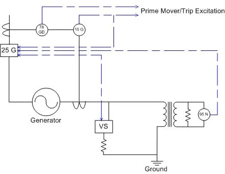
System Protection:
- 15G provides back-up protection for system machines connected to the ground bus.
- 15G will not provide back-up protection for the generator due to timing.
Generator Protection:
- Faults are detected by 78 GD.
- Low impedance ground path is opened by a switch (vacuum or air).
- The high impedance path to ground is the only available path after fault detection.
Additional Resources
- NEC Requirements for standby generators permanently installed in buildings. Read more in the grounding article from the NECA Director of Standards here.
- OSHA’s fact sheet on Portable Generator Grounding Requirements and Safety is also available.
Summary
Proper grounding is crucial for all engine-driven generator sets. Smaller portable sets can use simple earth grounds, but these provide no protection to the generator or devices. Impedance grounding is commonly used for medium and large systems, ranging from low to high impedance grounding, with hybrid systems incorporating the benefits of both. Compensated grounding offers the most advanced protection but is the most expensive. Once the appropriate system is selected, choose components that can handle the configuration safely and efficiently.