|
Single Generator Systems
Generator Set Operator Panel
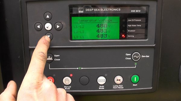 Operator Panels are included with generator sets and interface engine functions with generator functions. This allows for the engine and generator to be controlled by a single component. Operator panels provide the user with easy to view and use information, generator set controls and alarm and monitoring. Many suppliers offer options to panels such as AC metering and alphanumeric displays. Operator Panels are included with generator sets and interface engine functions with generator functions. This allows for the engine and generator to be controlled by a single component. Operator panels provide the user with easy to view and use information, generator set controls and alarm and monitoring. Many suppliers offer options to panels such as AC metering and alphanumeric displays.
Single Generator Set Components
Many styles of components are available for generator setup and configuration. Systems can be basic (Figure 1) or complex to include remote monitoring and networking. Below is an example of a basic system’s components:
• Generator Set – Comprised of engine and generator and houses operator panel.
• Operator Panel – Communicates with automatic transfer switch (for starting signal). Controls start, run and monitoring activities for engine and generator.
• Automatic Transfer Switch – Monitors power at switch panel. When a significant drop or loss of power occurs, switch signals generator set operator panel to start engine.
• Switch Panels – Distribute power to various circuits.
Loss of Power
When main power is lost the following events occur:
1. Automatic transfer switch signals generator set operator panel to start.
2. Operator panel starts the generator set and monitors engine and generator functions.
3. Generator supplies power to switch panels. Emergency power is distributed as designed.
4. When main power is available, automatic transfer switch disconnects generator set and connects to main power grid.
5. Operator panel controls engine run time to allow for cool down.
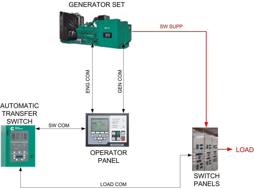
Figure 1, Single Generator Configuration
Multiple Generator Systems
HMI Panels
Human Machine Interface (HMI) panels can be used for multiple generator configurations. All individual generator set operator panels communicate with the HMI panel. These panels can monitor and control up to five separate generators simultaneously and can be equipped with paralleling capabilities.
Multiple Generator Set Components
Many styles of components are available for generator setup and configuration. Systems can be basic or complex to include remote monitoring and router setup. Below is an example of a basic system’s components:
• Generator Set – Comprised of engine and generator and operator panel.
• Operator Panel – Communicate with automatic transfer switch, engine and generator. Controls start, run and alarm and monitoring activities.
• Automatic Transfer Switch – Monitors power at switch panel. When a significant drop or loss of power occurs, switch signals HMI to appropriate generator set operator panels to start engine.
• Control and Paralleling Panels – House HMI panels, circuit breakers and switches use to distribute power to various circuits.
Using basic system components generators can be setup and configured in two different manners. Below are examples of Redundant Configuration and Parallel Configuration. Configuration possibilities are only limited by equipment capabilities.
Redundant Configuration
Redundant configurations are used when constant emergency power is essential to facility operations. Redundancy can be established with two or more generators. Primary generator(s) must be able to support facility load requirements. Secondary generator(s) must be sized to accept load requirements when a primary generator(s) fails.
Power Loss Redundant Configuration
Generator Set (A) and Generator Set (B) are primary generators. Generator Set (C) is the redundant generator (Figure 2).
When main power is lost or degraded and Generator Set (A) fails during operation, the following events occur:
1. Automatic transfer switch signals HMI panel to initiate startup of Generator Set (A) and Generator Set (B) via generator operator panels.
2. HMI panel monitors primary generator sets operations and parallels them into system operation.
3. Switch panels distribute emergency power as designated.
4. Generator Set (A) has active shutdown warning.
5. HMI panel initiates startup of Generator Set (C), Generator Set (A) is removed from configuration and cool-down/shutdown operation is performed.
6. HMI panel parallels Generator Set (C) with Generator Set (B), monitors system load and alarm condition for online generators.
7. When main power is available, automatic transfer switch disconnects generator set and connects to main power grid.
8. HMI Panel signals Generator Set (B) and Generator Set (C) operator panel to perform cool down/shutdown operations.
Parallel Configuration
Parallel configuration is more cost effective than a redundant configuration. In a parallel configuration generators are all primary generators and sized to meet load requirements without any redundancy. In this configuration if any generator fails, circuits must be isolated to reduce load requirements.
Power Loss Parallel Configuration
Generator Set (A), Generator Set (B) and Generator Set (C) are all primary generators.
When main power is lost or degraded and Generator Set (C) fails during operation, the following events occur:
1. Automatic transfer switch signals HMI panel to initiate startup of Generator Set (A), Generator Set (B) and Generator Set (C) via generator operator panels.
2. HMI panel monitors generator sets operations and parallels them into system to accept load.
3. Switch panels distribute emergency power as designated.
4. Generator Set (C) has active shutdown warning.
5. HMI panel initiates shutdown of Generator Set (C) and it is removed from configuration for cool-down/shutdown operations.
6. Circuits must be isolated to reduce load requirements.
7. When main power is available, automatic transfer switch disconnects generator set and connects to main power grid.
8. HMI Panel signals Generator Set (A) and Generator Set (B) to perform cool down/shutdown operations.
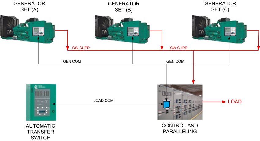
Figure 2, Multiple Generator Configuration
Remote Network Interfacing
Remote HMIs
Remote HMIs come in different models such as:
• Remote Unit – Unit can control generators in location remote from main control panel.
• Bar Graph – Displays graphical information on generator electromechanical performance.
• Annunciator – Provides visual and audible indications of alarms or status conditions.
Large generators can often be located in a room separate from switching room. For this example, annunciators are connected remotely in the switch room to allow for individual generator set monitoring (Figure 3). For critical operations a watch can be implemented to check generator operations during power failures.
Remote Monitoring
Installation of Remote Monitors allow for extended monitoring capabilities. Some capabilities include:
• Access user interface with multiple PCs for monitoring at multiple designated locations.
• Interface with smart devices for monitoring via WIFI.
• Send emails via SMTP, text via SMS to designated devices.
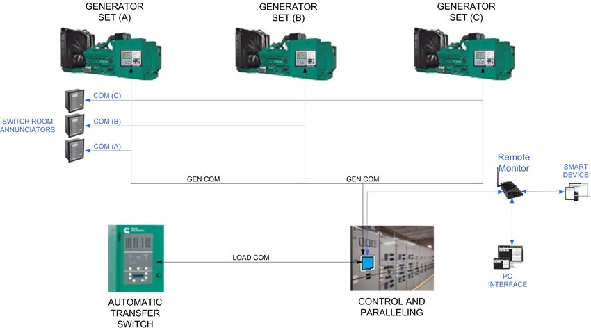
Figure 3, Remote Monitoring
|